|
Jean-François
FOURCADIER |
|
|---|
|
Jean-François
FOURCADIER |
|
|---|
| write
to me ! |
© 2000-2004-
J.F. Fourcadier
|
welcome page |
| high speed data | television | antennas | microwaves | repeaters | miscellaneous |
Did you say FHD22 ?
Not at all, FHD22 is not the call sign of a new french official station, broadcasting three times a week code lessons in PSK31 mode !
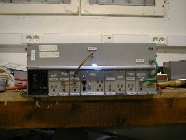
More seriously, the effervescence whose is the object the world of telecommunications with the development of mobile applications, high data rate and proximity transmissions led on a world level the Regulation Authorities to reorganize the uses of the spectrum in the neighbourhoods of 2 GHz. France and other european countries are obviously touched by the phenomenon. At a practical level, the 2.1 - 2.3 GHz band which was very largely used by small short range radio-relay systems must be released before the end of the year 2001. So hundreds, even thousands of equipments, are discarded. For example, the most widespread equipment in France is the radio-relay system FHD22, manufactured by Thomson or SAT in the years 1970-1980. It is crystal controlled, amplitude modulated (a switch in the antenna!), its transmitter power is 50 mW, the receiver IF is 119 MHz. Taking into account its type of modulation and its low transmitter power, it is not easily reusable as is for an amateur use. However, with its components you can build ham accessories for the 2.3 GHz band.
Perhaps a visit in the local scrap merchant will enable you to buy one of this equipment.
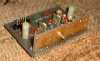
FHD22 radio-relay transmitter/receiver
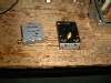
Elements to be salvaged :
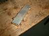
- the duplexer filter , made of silver plated brass, with interdigital lines
(click to enlarge)
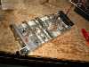
- the 2 GHz isolator and the 22 dB directive coupler carried out in microstrip
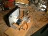
- the oscillator/quadrupler and the sextupler
The oscillator-quadrupler, starts from a (approximately) 95 MHz crystal, multiplies this frequency by four and delivers approximately 600 mW at 380 MHz. It is supplied by a 12 V DC PS. The sextupler operates with two stages equipped with varactor diodes. He delivers between 50 and 100 mW at 2.2 GHz.
- the mixer diode and its microstrip sandwich
- UT141 semi-rigid cables
Once these some components recovered, you can then show rare good manners while returning to the scrap merchant the 15 kilogrammes of metal sheets and various useless stuff which remain in your hands.
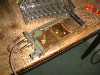
Achievements:
Realization of a 2.3 GHz filter
Very simple: Saws the rectangular section of the duplexer to approximately 25 mm of the SMA connector, then takes care to eliminate any trace of filings, and one closes again by soldering with tin endwalls, using a gaz blowlamp. Then setup the filter with a SHF generator or better with a sweeper. The filter response is sharp. Insertion loss: less than 2 dB. With a section one can build two filters.
Use of the oscillator-quadrupler and sextupler
Very simple: One replaces the 95 MHz (approximately) crystal by a 98 MHz one, one retunes the tuned circuits, one connects a 12 V DC power supply, and we get a source of 98 x 24 = 2352 MHz, with a power of some 70 to 80 mW. The signal with some - 20 dB spurious responses is not very clean, but one can arrange the things with the filter we describe previously.
Realization of a 2.3 GHz SWR meter
Very simple: one connects the RF output derived from the directional coupler on the RF input of the mixer diode. The output of this diode is connected on a microammeter (less than 100 µA). The power injected must be limited to a few hundreds of mW.
One can thus evaluate or measure the reflected power and setup 2.3 GHz antennas.
Good luck in your search and good achievements,
B5+ et 73 de Jean-François Fourcadier, F4DAY
As you can guess, english is not my mother-tongue. If you are living in UK or in the USA or in another english language country, you can help me to improve the quality of my website. Just send me an emailwith the mistakes you have detected (the biggest first ! ). Even one or two corrected sentences will be greatly appreciated. Thank you for your help !
© 2000-2004 J.F. Fourcadier F4DAY