|
Jean-François
FOURCADIER |
|
|---|
|
Jean-François
FOURCADIER |
|
|---|
| write
to me ! |
© 2000-2004-
J.F. Fourcadier
|
welcome page |
| high speed data | television | antennas | microwaves | repeaters | miscellaneous |
The POOR MAN's DIGITAL ATV TRANSMITTER :
Build this simple and cheap 70 MHz Exciter and start to transmit Digital Television !
Digital television transmitters generally call upon a complex signal processing sequence. However, it is possible to simplify considerably the circuitry if we stick to the essentials. Thus, we describe here a small circuit able to generate a digital amateur TV signal from pre-recorded video sequences on a PC hard disk or on a "cartridge" containing an EPROM.
To keep a simple structure for the Nyquist filter, and to significantly improve the ISI (Inter Symbol Interference) performance, an original circuit has been developed specifically to achieve this goal in a way that is easy to implement using pre-distortion of the modulating signals.
Summary of Exciter Features
This exciter will deliver a 70 MHz signal which will be easy to transpose to the 23 cm amateur band (1240 MHz - 1300 MHz). This will make it compatible with FTA (Free To Air) digital receivers which use the common DVB-S satellite standard. The RF signal is modulated by means of a four- state phase modulation (QPSK) method. The binary rate is fixed at 2.048 Mbit/s (European binary rate E1 standardized in telecommunications). On the signal input side, a DB-25 connector receives the request to send data and the data itself to be transmitted from the signal source.
The data source could be one of the following three options:
1. A PC with direct connection via the parallel port. The computer can store several tens of MB of data enough to transmit animated video sequences with audio of several minutes duration.
2. A "cartridge" including an EPROM (and a counter to sweep the addresses). The EPROM can contain a test pattern with animation and an audio signal.
3. Ultimately, perhaps, a Compact Flash memory stick could be used to store more than fifteen minutes of uninterrupted video and audio.
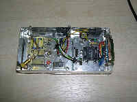
The exciter can be placed in a metal case approximately 148 x74 x 30 mm. (One suitable item available in Europe is known as the Schubert box). The exciter is fed with 12 VDC and the current drain is about 180 mA.
The serializer
Features
The serializer successively requests the data source (computer, cartridge, or compact flash memory stick) to send the bytes to be transmitted. These are sliced into packages of two bits (dibits) by the serializer in order to represent one point of four in the QPSK constellation. (One use of the word constellation is to suggest the several data points one sees on a scope, just as many stars are seen in a constellation). The serializer contains the main bit clock and generates the various secondary clocks needed by the system, that is: request for a new byte every 3.906 µs, output of a dibit every 0.977 µs to the QPSK modulator. The master clock, integrated in the serializer module, is fixed very precisely at 2.048 Mbit/s, the binary rate on the radio channel. This results in symbol rate of 1.024 MBaud.
The serializer includes useful additional features for the setting of the QPSK modulator and control of the modulation. It can, when requested, generate two I and Q signals of 90° lead or 90° lag, or pseudo-random modulating signals.
It is worth noting that the serializer provides, in addition to the I and Q modulating signals, two I* and Q* auxiliary signals for which the objective is to correct the step response of the summary Nyquist filters located on the printed circuit board of the QPSK modulator. It will be seen that one can thus obtain at a lower cost a substantial reduction in the inter-symbol interference (ISI).
How tthe serializer operates
Two eight- bit registers A and B are connected alternatively, every 3.906 µs, to the parallel port of the PC. These registers store the data from the computer. These two registers are sequentially read, 2 bits by 2 bits, every 0.977 µs and the dibit thus obtained is sent to the QPSK modulator input to form one point among four of the constellation.
Improvement of the intersymbol interference by predistorsion of the I and Q modulating signals
To correct the total response of the channel filter (5th order Butterworth filter in the transmitter, plus root raised cosine filter in the receiver), it is necessary to create and apply to the QPSK modulator the dual pre-distortion signals I * and Q * which minimize the inter-symbol interference. After in-depth studies of this phenomenon, we see that the correction signals I * and Q * must be precursory signals with levels reversed compared to their references I and Q with an advance of one symbol duration.
We will see below that this provision is very simple to implement. It only uses two wires and two weighting resistors added to the assembly. It makes a spectacular improvement in the reduction of inter-symbol interference.
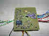
Practical serializer creation
- schematic diagram
(click to open the schematic)
The diagram requires few comments. The principal components are two: a low cost CPLD Altera EPM7064SLC44-10 and a quartz crystal oscillator on 8.192 MHz. As the CPLD is very sensitive, one will endeavor to carefully decouple the power supply pins using several SMD capacitors of 2.2 nF and 100 nF. The printed circuit is designed like that of a high frequency circuit with a large ground mass and many places for through- the- board connections.
To simplify PCB building (1-1/2 sides), some connections will need to be made very carefully using small diameter insulated wire. A 5 V regulator ensures the stabilization of the supply voltage. A jumper permits choosing 1 of 5 operating modes: three modes of adjustment (90° lead, 90° lag, pseudo-random generator), an operating mode (DB-25 external input) and a Continuous Wave (CW) mode, obtained by simply withdrawing the jumper. It may be possible to directly connect a 1 pole 5 position switch for choosing the desired operating mode from the front panel of the transmitter. Pay attention to avoid reversal of the I* and Q* wires !
- printed circuit
download the printed circuit, Eagle or bmp format (33 kB zipped)
Logic diagram of the CPLD configuration
The logic diagram can be read by opening the file "serialisateur2.gdf", provided below, by means of the Maxplus+ II software by Altera. The logic diagram comprises six major parts:
- a serializer whose central function is a double multiplexer with 8 inputs and 2 outputs. The diagram shows the synoptic of the serializer,
- a pseudo-random data generator which provides in serial form a succession of 32767 bits. It is followed by a de-serializer which produces the groups of 2 bits IQ,
- a square signal generator for signals of 90° lead and 90° lag,
- a multiplexer with 5 inputs and one user selected output which makes it possible to select the data source or mode,
- two output D flip-flops which, by their synchronous operation, guarantee the precise timing of the output signals. The first D flip-flop is used to produce the logical pre-distortion signals I* and Q*, the other to deliver signals I and Q,
- and finally, a synchronous counter provides all the various clock signals necessary for unit operation.
Programming
The transfer of the configuration in the CPLD is achieved using the Maxplus+ II software and the "ByteBlaster" programmer. The latter is connected between the parallel port of a PC and the 10 pins located on the printed circuit serializer. The "ByteBlaster" programmer and the transfer procedure were described in a in a previous article.
The transfer is fast just a few seconds.
QPSK modulator
The QPSK modulator was already fully described (diagram, printed circuit, adjustments) in a previous article to which the reader is invited to refer.
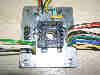
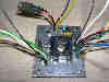
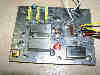
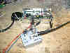
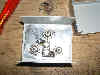
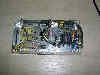
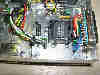
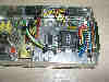
Building the exciter and making the interconnections between the circuits
The two printed circuits are fixed in an aluminum or metal box of 148 x 74 x 30 mm. In Europe, a Schubert box is available. The two 7805 voltage regulators are placed against the wall of the case which acts as a heat sink. A feed-through capacitor of 1 nF passes the + 12 VDC power to the circuit board.
A male DB-25 socket connects the transmission bytes which come either from a cartridge containing an EPROM, or from the parallel port of a PC. The DB-25 connector also links the control signal flow which is transmitted on the ACK wire. The wiring of the DB-25 connector complies with the standard adopted for PC parallel ports.
Note: pay strict attention to avoid reversal of the wires transmitting the I* and Q* correction signals (and also to the I and Q wires to which they are referred). The correction could no longer be assured and the remedy would be even more painful.
The integrated test generator
The absence of a jumper produces a pure carrier at 70 MHz.
The first two positions of the jumper correspond to adjustment signals of the QPSK modulator: 90° lead and 90° lag. Therefore one will see, under these conditions and good QPSK modulator setup, an output at 70.256 Mhz being + 256 kHz from the carrier (respectively 69.744 Mhz being - 256 kHz from the carrier). The carrier and the undesired sideband will be completely cancelled during the setup process (see more details on the QPSK modulator page).
The next to last position produces a pseudo-random test signal, whose spectrum is similar to that of a digital television transmission. Finally, the 5th and last position authorizes the entry of the data to be transmitted to the DB-25 input connector.
(click on the labels to enlarge)
The constellation
It was able to connect this 70 MHz QPSK exciter to a professional test equipment to visualize the constellation such as it is seen by a general public-use digital satellite receiver with root raised cosine filtering where alpha = 0.35. By transmitting a pseudo-random sequence using the integrated test generator, one can see the constellation.
Hereafter, the constellation is obtained without using pre-distorsion, i.e. with I* and Q* inoperative (logical input I* connected to the I logical input and logical input Q* connected to the Q logical input):
Inter-symbol interference is relatively important issue. One can detect that each point of the constellation is in fact made up of four groups of points.
By connecting the pre-distortion now, that is, by connecting I * and Q * inputs at the dedicated outputs of the CPLD, one notes a spectacular improvement in the inter-symbol interference reduction:
The optimum result is obtained by adjusting the weighting resistances R29 and R30 on the QPSK modulator for the best constellation. The correct value for R29 and R30 is 1.5 kohm.
Connection to a computer
Connect to the PC parallel port using a short cable with CB-25 connectors. There is a male connector at one end and a female connector at the other end. The cable must contain at least 10 wires and its length should not exceed 60 cm to avoid affecting the transmission quality of the fast signals (indeed, a byte travels within the cable every 3.9 µs).
Software and files
The PC must store on its hard disk the data to be transmitted, then it needs for fast access to transfer the data to RAM before any transmission. In order to ensure control of the data flow, the PC must scan the ACK wire of its parallel port and present a new byte at each change of logic level on ACK. For these reasons, it is necessary to run a small management and dialog software in the PC. Information relating to the operating system and the software was given in a previous article.
The video files are developed using the Manzanita software (free in demo version) and the TS188ToIQ.exe software written by Evariste, F5OEO. The details of building the files were provided in a previous article.
The reader in a hurry to visualize images will find hereafter an IQ file, ready- to- play, representing a bar test pattern.
download the bar test pattern "test.psk" (333 kB zipped)
Note: The above file provides IQ data ready to be injected into the serializer. It is planned for a binary rate of 2.048 Mbit/s on the radio channel, S/R = 1.024 MBaud, FEC = 1/2, PAL system, 25 frames/s. The video bit rate is 800 kbit/s. The file represents a bar test pattern with some animation to allow the detection of pictures freezes. Its duration is 2 seconds. For a continuous transmission, it is necessary to loop the end to the beginning with the PC software.
Transmission of digital television signals
The final goal is of course to create a genuine digital transmitter which will use the present 70 MHz exciter, transposition, filtering and finally linear RF amplification.
However, one can, as of now, start to visualize images by connecting the exciter output to a simple balanced mixer fed by an oscillator generating a local oscillation with F-70 MHz or one of its sub-multiples. Thus a 300 MHz oscillator with an output level of + 7 dBm will be able to beat with the 70 MHz signal from the exciter to generate a signal of (300x4) + 70 = 1270 MHz. The transmitted level is not very important, but a small antenna connected directly at the output of the mixer will make it possible to transmit the digital TV signal out to a range of several meters.
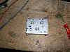
The aluminum case, provided above with three BNC connectors, contains a simple SRA-1 balanced mixer. It is a useful accessory!
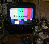
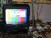
So quick, let's connect the computer, let's setup the FTA digital receiver, and..... here is the result !
Conclusion
This little 70 MHz exciter, without any pretensions, calls only for readily available and inexpensive components. With a little care, building the printed circuits is entirely possible for anyone with amateur means, i.e. inkjet printer jet for the films, horizontal tub, and iron perchloride for etching. The result is a unit making it possible to start some very interesting personal experiments in the field of amateur digital signal transmission. The description of the data "cartridge" will be the subject of a forthcoming article. The unit will then be autonomous.
Gentlemen, start your soldering irons !
Translation from the French article with the friendly help and advice of John Jaminet, W3HMS
B5+ et 73 de Jean-François Fourcadier, F4DAY
As you can guess, english is not my mother-tongue. If you are living in UK or in the USA or in another english language country, you can help me to improve the quality of my website. Just send me an emailwith the mistakes you have detected (the biggest first ! ). Even one or two corrected sentences will be greatly appreciated. Thank you for your help !
© 2000-2004 J.F. Fourcadier F4DAY